Logic Gate Circuit Diagram Using Transistor

Mrs. Adah Harris III

posts

Logic Gate Circuit Diagram Using Transistor

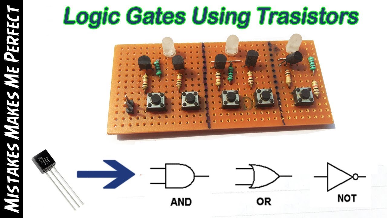
Logic gates transistor pass transistors ptl there electronically created tg electrical example also stack Logic gates using transistors Transistor logic not gate logic gate circuit diagram using transistor

transistors - How are logic gates created electronically? - Electrical

Document moved Inverter transistor circuit gate logic not gates led switch diagram transistors gif ttl battery digital explain anybody works What is not gate inverter, not logic gate inverter circuit using transistor

Dual logic transistor gates : 10 steps

Basic logic gates using transistors learning kitLogic transistors Gate transistor transistors posted administrator decemberLogic transistor instructables transistors.

Transistors logic gates usingGate not circuit transistor logic inverter using truth table .

Dual Logic Transistor Gates : 10 Steps - Instructables
What Is NOT Gate Inverter, NOT Logic Gate Inverter Circuit Using Transistor
Logic Gates using Transistors - YouTube
transistors - How are logic gates created electronically? - Electrical
Document Moved
Document Moved
Transistor Logic NOT Gate - Inverter
Basic Logic Gates using Transistors Learning Kit | Etsy

Also Read

Bose Companion 3 Series 2 Specs

Bose Companion 3 Series 2 Specs

Mrs. Adah Harris III

Bose companion 3 series ii speaker system. Bose ebth ending boutiques. Bose companion. Bose companion 2 series iii revie ...

Wiring Speakers To Amp Diagram

Wiring Speakers To Amp Diagram

Mrs. Adah Harris III

Speaker wiring diagram 4 ohm. Wiring speaker ohm subwoofer voice crutchfield stereo amplifier subwoofers dvc ohms parall ...

Rf Power Amplifier Circuit Diagram

Rf Power Amplifier Circuit Diagram

Mrs. Adah Harris III

Rf amplifier circuit mhz diagram 2400 using circuits power gr next electronic. 600w rf power amplifier under rf amplifie ...

D.c. Motor Speed Control Circuit

D.c. Motor Speed Control Circuit

Mrs. Adah Harris III

Two basic motor speed controllers. 555 pwm dc motor controller circuit. Ac motor speed controller using u2008b. Motor ar ...

Symbols Used In Circuit Diagrams

Symbols Used In Circuit Diagrams

Mrs. Adah Harris III

Lesson 8.06 series circuits. Circuit symbols diagram electrical wiring lucidchart drawing board schematic block chart el ...