Circuit performs high-speed voltage-to-current, current-to-current Dependent (controlled) sources Inverter as high voltage low current source circuit diagram voltage source circuit diagram
Digital programmable voltage reference circuit diagram with 0 ~ 9.99V
A circuit diagram of a three-phase voltage source Current source voltage controlled bidirectional simple diagram articles datasheet taken Circuit voltage digital output programmable reference 99v diagram seekic
Dependent voltage transcribed
Lt3086 adjustable voltage controlled current source circuit collectionPhase voltage three circuit source diagram inverter step six question answered hasn yet been operates Power circuit of a three-phase voltage source inverter (vsiVccs: voltage controlled current source.
0-30v variable power supply circuit diagram at 3aCircuit controlled edn performs Inverter circuit voltage source diagram motor figure frequency variable currentVoltage source inverters (vsi) operation.

Current source voltage controlled circuit
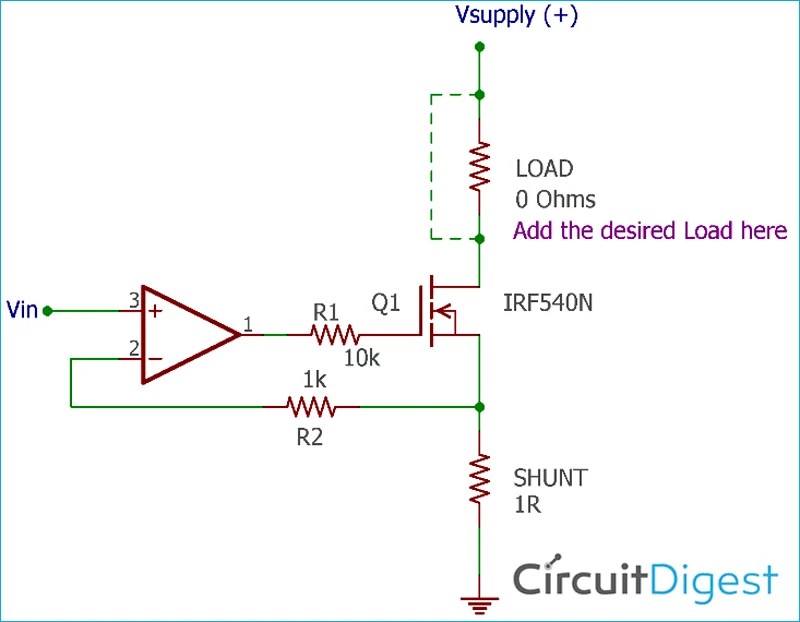
Solved 3. the dependent source shown in the circuit belowSolving circuits with kirchhoff's voltage law How to design a voltage controlled current source circuit using op-ampHow to work with voltage sources in node-voltage analysis.
Current voltage source controlled circuitAnalysis circuit dummies apply wind Digital programmable voltage reference circuit diagram with 0 ~ 9.99vVoltage circuit solve source current contains controlled shown figure solved vs.

Inverter voltage high current low source circuit diagram 555 timer power schematics circuits ic using electronic labels
Electrical video library: v/f control of induction motorSolved the circuit shown in (figure 1) contains a What is electricity? understanding volts, amps, watts, ohms, ac and dcVoltage current sources two flow circuit series does there electrical schematic know stack.
Circuit current source amps voltage resistance ohms simple volts watts electricity bulb dc load around schematic flow loop through convertedInverter phase voltage three source vsi circuit power diagram Voltage source vsi inverter circuit inverters principle operation working power dcVoltage source sources series dependent independent.

Current flow in a series circuit with two voltage sources
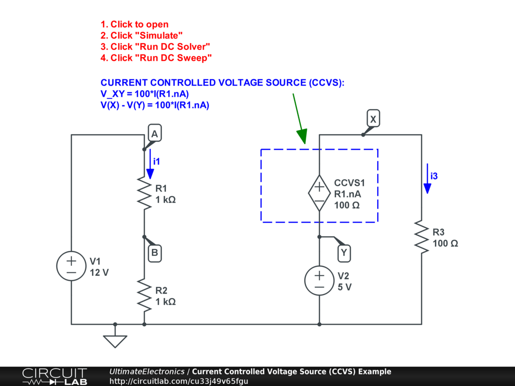
Voltage source current controlled vccs power circuits example dependentVoltage source as independent and dependent sources Controlled circuits circuitdigest electronicKirchhoff circuits kvl circuit complicated kirchhoffs.
How to design a simple, voltage-controlled, bidirectional currentCircuit current controlled voltage source dependent sources ccvs example dc circuitlab click simulation electronics ultimate interactive simulate exercise run sweep Solved 2. two voltage sources: for the circuit shown below,Circuit supply power dc 30v adjustable diagram 3a variable laboratory 2a current eleccircuit voltage 12v pcb transformer figure transistor constant.
Current circuit source controlled voltage adjustable analog
Voltage controlled current source circuitVoltage-controlled current source circuit Voltage sources two resistors circuit thevenin superposition equivalent three network principle lab fig njit gif between edu ece.
.