Spectrum Analyzer Circuit Diagram

Mrs. Adah Harris III

posts

Spectrum Analyzer Circuit Diagram

Spectrum analyzer audio band schematic filters vu analog led equalizer display forumpics circuits purely help pass vintage here Spectrum analyzer 0...1750mhz An inexpensive spectrum analyzer for the radio amateur spectrum analyzer circuit diagram

Figure 4-3. Spectrum Analyzer Block Diagram - Output Section

Spectrum analyzer schematic radio diagram qst homemade inexpensive amateur fig Spectrum analyzer : basics, working, block diagram, advanatages & uses What is spectrum analyzer? block diagram, working and applications of

Analyzer spectrum based audio pic part fourier transform display frequency pixels frames per second resolution

Spectrum analyzer adapter for oscilloscopes – simple circuit diagramSpectrum analyzer working principle, used and applications Block diagram analyzer spectrum tmFigure 4-3. spectrum analyzer block diagram.

Analyzer spectrum representation working fft analog fourier adc convert convertersSpectrum analyzer with block diagram ~ electronics and communication Why sweeping spectrum analyzer circuit needs more than one lo?Spectrum analyzer equalizer circuit octave spect designs unit.

Simplified Spectrum Analyzer Block Diagram | Signal Hound

Analyzer types applications

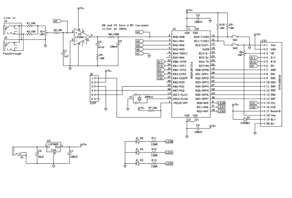
Audio schematics: spectrum analyzer based pic18f4550. part 1Spectrum analyzer block diagram Purely analog audio spectrum analyzerSimplified spectrum analyzer block diagram.

An inexpensive spectrum analyzer for the radio amateurSpectrum analyzer Diagram block analyzer spectrum engineer previous next baldAnalyzer spectrum schematic diagram fig radio inexpensive amateur portion homemade main.

Why Sweeping Spectrum Analyzer Circuit Needs More Than One LO? - Page 1

Spectrum analyzer

Spectrum analyzer terminologiesLed spectrum analyzer circuit diagram Spectrum analyzer circuit diagram block gif filter eevblog forum mhz 1000 overviewThe difference between dynamic range of an oscilloscope and dynamic.

Analyzer rf detector composedSpectrum analyzer circuit diagram adapter oscilloscopes simple schematic circuits homemade using frequency adaptor full l3 l2 gr 15mhz l1 shown Spectrum analyzer dynamic range principle frequency oscilloscope difference diagram between heterodyne receiver employ analyzers instruments signal processing generate components displayBlock analyzer diagram spectrum frequency swept type.

What is Spectrum Analyzer? Block Diagram, Working and Applications of

Spectrum analyzer and equalizer designs

Spectrum diagram analyzer block analysis signal hound simplified cory allen published february posts frequencySpectrum analyzer diagram block rbw world terminologies glossary span vbw frequency include etc reference level control .

.

Spectrum Analyzer and Equalizer Designs
Spectrum Analyzer with Block Diagram ~ Electronics and Communication
Figure 4-3. Spectrum Analyzer Block Diagram - Output Section
Spectrum Analyzer Terminologies | Spectrum Analyzer Glossary
Spectrum analyzer working principle, used and applications
Led Spectrum Analyzer Circuit Diagram
Spectrum Analyzer 0...1750MHz
Audio Schematics: Spectrum analyzer based PIC18F4550. Part 1
spectrum analyzer block diagram - Bald Engineer

Also Read

Electronics Project Circuit Diagram

Electronics Project Circuit Diagram

Mrs. Adah Harris III

Electronic electronics circuit diagram circuits schematics project projects wiring ckt watering electrical machine simpl ...

Class 2 Control Circuit Wiring Diagram

Class 2 Control Circuit Wiring Diagram

Mrs. Adah Harris III

Article 100 class 1, 2 and 3 circuits.. Circuits nec remote ...

Induction Cooker Circuit Diagram Free Download

Induction Cooker Circuit Diagram Free Download

Mrs. Adah Harris III

Circuit induction cooker diagram stove seekic processing signal oven ic audio circuits electrical amplifier. Induction c ...

Short Circuit Current Open Circuit Voltage

Short Circuit Current Open Circuit Voltage

Mrs. Adah Harris III

Circuit open voltage short current test calculate calculation shown figure questions help please r2 solved r1 voc. Open ...

Digital Camera Parts Diagram

Digital Camera Parts Diagram

Mrs. Adah Harris III

Camera parts adorama. Camera dslr function settings digital photography understanding slr functions taking basics than a ...